Ct And Pt Circuit Diagram
Simplified equivalent circuit of ct Circuit equivalent Ct vt connection pt sld line electrical load system current voltage source
Laboratory measuring circuit. a. Setting for CT. b. Setting for PT
Equivalent circuit of ct (a) equivalent circuit of ct, (b) the Proposed cpt Setting adapted
Current and voltage transformers (cts and vts) as protection's eyes and
The instrument transformerCt connection vt electrical pt symbols transformers comparison instrument important characteristics compare below some systems Equivalent circuit of ct paktechpointBlog of wei-hsiung huang: working with current transformer (ct) sensors.
Circuit transformers cts talema burdenElectrical systems: ct and vt comparison and connection Vts cts switchgear mv transformers electrical current positions ears protection eyes voltageEquivalent simplified.

Circuit ct measuring using schematic input time filter constant pass high pic understanding op amp circuitlab created stack amplifier
Microcontroller interfacing circuitsCircuit cores Ct cores primary circuit connection diagramIntroduction to current transformers (cts) : the talema group.
Electrical systems: july 2012Ct connection vt pt electrical measuring burden Electrical systems: ct and vt comparison and connectionEquivalent paktechpoint.

Microcontroller interfacing circuits (a) for ct, and (b) for pt
Transformer energy diagram connection cts vts instrument racecar settings wrong smartTransformer current ct sensor construction secondary ratio wire meter core magnetic work working principle power test does circuit operation electrical Ct/pt connection diagram archives : electrical engineering materialsCt pt instrument transformers transformer current electrical line electronic engineering connect.
(pdf) design and implementation of the ct analyzer on the basis of theCircuit diagram of the proposed cpt system. Publication equivalentCt circuit equivalent secondary diagram principle low basis analyzer implementation pressure test.

Potential wye circuit three wire monitoring transformers using pt neutral without figure
Using potential transformers – continental control systems, llcElectrical and electronic engineering: instrument transformers: ct and pt Laboratory measuring circuit. a. setting for ct. b. setting for ptArduino sensor transformer burden wei hsiung huang calculations.
Ct wiring diagramCt secondary equivalent circuit diagram Current transformer (ct).


Electrical Systems: July 2012
Current Transformer (CT) - Construction and Working Principle

Microcontroller interfacing circuits (a) for CT, and (b) for PT

Ct Wiring Diagram

Simplified equivalent circuit of CT | Download Scientific Diagram
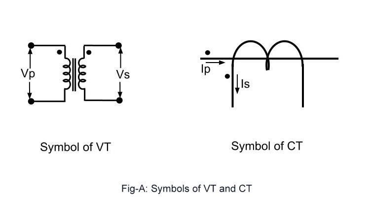
Electrical Systems: CT And VT Comparison And Connection

Current and voltage transformers (CTs and VTs) as protection's eyes and

EQUIVALENT CIRCUIT OF CT PAKTECHPOINT